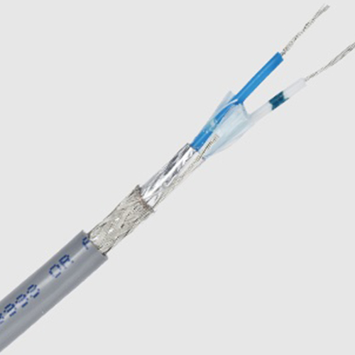
Enhance Your Rs485 Cable Abilities
페이지 정보

본문
So, for eight data bits with a parity bit, M would be set (equal to one) in order to add an extra bit to each byte transmitted, and PE would be set in order to make that extra bit be used as a parity bit. When PE is set (equal to one), the most-significant bit in each byte transmitted will be a parity bit that is either set or cleared by the serial port automatically in order to achieve even or odd parity. This is an extra single bit appended to the end of each byte or character transmitted, which is set or cleared as necessary to ensure that the total number of '1' bits in the byte is always odd or even. If PT is cleared, then all transmitted bytes with a parity bit will have an even number of total '1' bits. Parity checking is not often used, because it is not a robust method of error detection. If two bits are received incorrectly, the error will go unnoticed by parity checking. The PT bit, with mask 0x01, determines whether even parity or odd parity is used if parity bit generation is enabled.
In either of these cases, a source of noise that caused one bit to be received incorrectly would invalidate the received byte, since the total number of '1' bits would be odd rather than even. The M bit, with mask 0x10, determines whether eight or nine bits total are transmitted with each byte, regardless of whether or not the most-significant bit is a parity bit. The PE bit, with mask 0x02, determines whether the most-significant bit in each byte is used as a parity bit. The above parity settings will also determine how incoming data is interpreted (whether the most significant bit is considered a parity bit or part of the data being transmitted, and how many bits total to expect in each byte). If PT is set, all transmitted bytes with a parity bit will have an odd number of total '1' bits. Rather, the UART deduces the correct time to sample the incoming signal based on the start and stop bits in the signal itself. In other words, each local UART on the wildcard can both send data to and receive data from a remote UART on the other end of a connecting serial cable. Resistive termination - If the PDQ Board is at the end of the RS485 cable you can terminate the cable by installing jumper caps at both jumper locations, "Term" and "RTerm".
In that case, when using very long cables you can improve noise immunity and assure a valid idle level when the transceiver is not active by installing bias resistors. Bias termination - Using resistive termination decreases noise immunity, particularly if the cable is loaded with many devices. The end devices are responsible for terminating the cable so that there are no reflections from the cable ends. No termination - If the PDQ Board is not an end device, you should not terminate that cable. The other end of the cable should be terminated similarly. Because we chose the default baud rate (which the terminal is presumably already set for), you can simply move the serial cable from the Serial Port 1 connector to the Serial Port 2 connector on the Docking Panel to complete the change to the new port. We assume that you are now communicating with the PDQ Board via the default Serial1 port at the standard 115200 baud rate. Serial1 port the default startup serial link. In this case, cable connections may be made to Serial 2 at pins 4 and 10 of the PDQ Board’s 10-pin Serial Header, or pins 5 and 6 of the Docking Panel’s 10-pin right-angle Serial Header.
The terminal program communicates with the PDQ Board via this serial port. The USE.SERIAL2 command means that the operating system’s terminal interface now communicates via Serial2. Enabling RS485 on the Serial2 port is parallel to the process described above. They should generally not be needed, except if you use long cables, multiple RS485 devices, and resistive termination. Slave devices use the master in/slave out pin, MISO, for transmitting, and the master out/slave in pin, MOSI, for receiving data. The interface can be used to support analog to digital and digital to analog converters, networks of many computers controlled by a single master, or networks of devices controlled by several coordinated masters. The remaining inactive slaves may actively receive, or listen to, data on the communications line, but only one slave at a time can transmit a message. While running this program, the parity settings of Mosaic Terminal may be adjusted, and in each case the message that matches current settings will appear clearly while the other messages will appear garbled. 1 running at the prior established baud rate (typically 115200 baud). If it doesn’t, confirm that the terminal’s baud rate is correct by selecting the Comm item in the Settings menu of the Mosaic Terminal program, and click on 115200 baud.

- 이전글How To 출장마사지 The Planet Using Just Your Blog 24.07.05
- 다음글Slot Machine Grid Betting - Casino Strategics 24.07.05
댓글목록
등록된 댓글이 없습니다.


 블로그체험단 바로가기